|
Internal Rotator Control interface.
The internal rotator control interface is a relatively recent introduction and offers control of Hy-Gain and Yaesu type rotors.
Options for GS232A, GS323B and DCU-1 protocols plus their derivitives are offered , which covers many rotator types which share these protocols.
Other control protocols may be added in the future depending on interest.
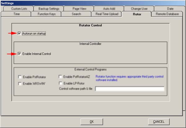
The toolbar button is only displayed when rotor control is enabled.
Menu/Options/Settings/Tab - Rotator.
The interface provides positioning of the rotor to the current Log 'QTF' azimuth generated by a Callsign entered by using the Winlog32 toolbar button.
A 'Rotate To' option is offered in the DXCluster mouse right-click menu function.
Positioning can be controlled directly from the Rotator window.
Options and Settings.
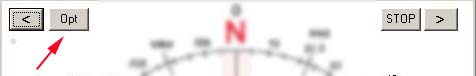
The interface settings are accessed via the 'Opt' button on the Rotator window.
Tab - Set-up.
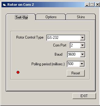
Select the rotator protocol type from the drop-down list.
Individual rotator makes and models are not listed, only the protocols used, if you are not familiar with which protocol your rotator or interface uses, check the documentation or experiment.
Select the com port your rotator interface is using from the drop-down list.
Select the baud rate from the drop-down list.
The baud rate MUST match that used by the rotator interface (check documentation), otherwise nothing will happen.
Select the polling period, this sets the frequency of requesting positional data from the rotor interface - the setting value is in milliseconds.
if you are not sure how to set this, a value between 500ms and 1000 (1 second) usually works best but if unsure leave the default setting value.
Keep in mind that shorter polling periods (lower values/faster polling) will use more system resources unnecessarily.
Tab - Options.
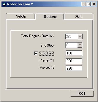
Total Degrees Rotation/End Stop
These options are not available at present.
Auto Park.
A predefined position, which can be called with a mouse right-click and selected from pop-up menu in the Rotator window.
When auto park is enabled the rotator will turn to the pre-defined park position when closing the rotator window or closing Winlog32.
Presets.
Preset-1 and preset-2, pre-defined positions which can be called with a mouse right-click and selected from the pop-up menu in the Rotator window
Tab - Skins.
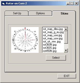
Select your preferred background image for the rotator window.
A selection of basic compass and map images are included. the end user is encouraged to add a custom image of their own.
Great circle map images can be generated from your QTH using resources such as NS6T Azimuth map generator page.
Image files should be processed in an image editor and must conform to a square format jpeg similar to the image size and format supplied, the file name must start "rot" e.g. "rot_MyImage.jpg"
Image files must be included in the folder ..\winlog32\PicSnd\
Using.
The rotator window.
The control window can be resized and positioned as required.
In the illustration, a great circle map of the earth is chosen with the UK as the centre point, see 'skins'.
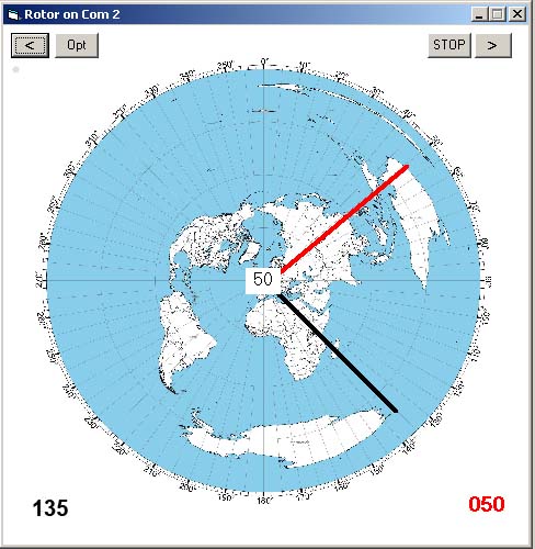
| ^ Current azimuth (black line) |
^ Requested azimuth )red line) |
The black line will show the present position of the rotor where feedback from the controller is available, this is not available on all control interfaces.
The red line shows the requested position.
Turning the antenna with the Rotor control box manually will display the current position of the rotor/antenna in real-time (black line).
The rotor indicator 'led' will turn red when the rotor is turning and back to green when halted.
The Winlog32 main toolbar rotate icon will also turn red when the rotor is moving. N.B. Only when supported by protocol
Control from the Rotator window.
Left(CCW), Right(CW) and Stop buttons
Send respective commands to turn the rotor to the end stops, the rotor can be halted at any point by clicking the L/R buttons or the stop button.
Where positional feedback is available the black line will show the rotor position in real-time.
From the mouse and cursor.
Moving the cursor around the Rotator window will show the azimuth degrees in the central display.
Clicking a position within the window will set the red pointer to the requested position and command the rotor to turn to it.
Where positional feedback is available the black line will show the rotor position in real-time.
The rotor can be halted at any time using the Stop button.
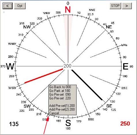
 right click for menu. right click for menu.
Right-click within the Rotator window will display a menu from where you can select:
'Go Back'; return to the previous position.
'Go Park'; move to the pre-defined 'Park' position, as set in Options.
'Go Pre-set(s)' move rotor to pre-set position, as set in Options.
'Add Pre-set(1)' & 'Add Pre-set(2)' set pre-set position to the present position.
'Cancel'
From the Log.
Enter a callsign and 'enter', click on toolbar button to move to indicated azimuth, for VHF this will be more accurate when the grid locator has been added to the Remarks field.
From the DXCluster window.
Select the callsign field and use the right-click menu item "Rotate to", rotator will move to corresponding azimuth.
NOTES.
As feedback from the rotor hardware relies on analogue voltage to digital converter (ADC), inaccuracies in the positioning are likely,
this is outside the control of the software.
Any inaccuracies from the ADC can give erratic readouts on the Rotator display, these are often due to dirty contacts
on the rotor feedback potentiometer or 'noise' generated and induced into the control wiring.
Protocols GS232A and basic DCU1 to not offer 'feedback' of rotor azimuth when rotor is turning, in these cases only commands to turn the rotor to a position will be possible.
|