|
RIG CONTROL INTERFACE - TENTEC
The Rig Control Window (RCW) interface included with Winlog32 supports Tentec Omni VII and Orion rigs.
Pegasus is supported via the Pegasus F/T (File Transfer protocol) - see relative notes at end of this section for setting up the Pegasus.
These rigs can be controlled using a RCW.
The interface has only been tested with these two types, but may work with other compatible models.
Menu/Rigs/#1:TenTec
Principal Features:
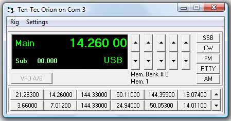
Main display of transceiver VFO and sub VFO frequency.
Display of Main VFO and mode setting.
VFO display tracks rig frequency and mode automatically with resolution to 10 Hz.
Automatically sets Log band and frequency.
Frequency display offset option for transverters.
Switch Rig VFO A/B.
Set transceiver frequency and mode from the Control Window.
Control with main, midi or mini window or hide.
Store 240 software memories with Frequency and mode in 20 banks of 12 memories.
Instantly transfer memory to VFO by clicking appropriate memory button.
Select and drag frequency/mode from VFO display directly onto memory buttons.
DXCluster frequency can be transferred from DXCluster window display by clicking on the
Frequency field in the DXCluster window.
DXCluster Band View can track VFO and band.
SET-UP
(Peagsus - see relative notes at end of this section).
It is anticipated that you will be familiar with the requirements to
use the CAT interface with your transceiver, if not read the relative section in the
transceivers' manual.
The transceiver is controlled via a cable from the computer serial "COM" port,
you will need to ascertain an unused Com Port on your computer before starting.
You can also connect the software via a USB cable using a Virtual Com Port (VCP) and associated driver installed on your PC.
SETTING UP A TENTEC RIG FOR THE FIRST TIME.
Connect your transceiver to the computer via the Com Port.
Verify ALL CAT Settings on your transceiver (see manual on how to do this).
Open the Tentec RCW.
menu/Rigs/Tentec
RCW menu/Rig/Set-up.
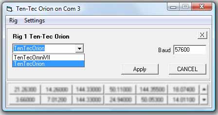
Select your rig from the 'Select Rig' List, this will approximate
the settings required.
When a rig is selected the baud default value for this rig is displayed, a different value may be required,
click on the 'APPLY' button and close the Rig Settings window.
RCW menu/Settings/Com Port
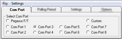
Select a Com Port, identify which com port to use - this may be Com 2, 3 or 4 but with VCP it could be any number.
Select Peagasus F/T (com ports disabled) only for the Pegasus rig type.
This option will display a dialog box for the file path where the file for this protocol will be stored.
If the file path is not set - it will not be possible to enable this option.
See end of this help section for notes on setting up for the Pegasus F/T
If the rig Control interface can not open a Com Port you will get an
error reported in the RCW heading " Error on Com Port: #", if this
occurs then you will need to correct your Windows settings and/or hardware so that the required
Com Port can be selected without an error.
Polling Period.
RCW menu/Settings/Polling
These Tentec rig models require software polling, each set period the software asks the transceiver for
data and processes the reply.
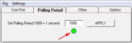
The default polling period is set to 1000 milliseconds (one second), in most cases this
can be reduced to provide smoother tracking of the rigs VFO changes.
Shortest polling period is 100 Milliseconds, polling period is in the 'set polling period'
box, pressing the APPLY button will set new polling period, the green 'LED' will blink at
the same rate as the polling period.
RCW menu/Settings/Settings

Baud.
Ensure the Baud Rate selected is the same as that being used by the Rig.
Delay Value
The Delay Value setting may need changing if the mode is not changing
correctly in the VFO display. Faster computers may need this value to be increased, slower
computers may need the value decreased.
Enable RTS.
This option should be enabled if the cable interface is powered from the Com Port.
Enable DTS.
This option is not normally enabled.
Stop Bit.
Option to select the stop bit, the interface may work on either option, but if the default setting does not work try the other option.
It is probable that faster baud rates may require the stop bit setting of "1".
Start at Memory Bank (#).
This will pre-select a memory bank on starting the RCW - see separate section on the Memory Banks.
This option would only be required when using multiple RCWs.
Use with a Transverter.
Transverter Offset MHz.
Settings - Other "Transverter IF Offset"
Set to option to 0 if no transvert action is required (default) or select the IF offset from drop list.
to enable.
Offset = Transverter Output Frequency - Rig Output Frequency.
The transverter output frequency will be displayed in the VFO window and also will
be added to Log.
Only upward transverting is supported.
RCW menu/Settings/Options

Start Rig Interface on Start-up.
The RCW will automatically start on running Winlog32.
Start with window minimised.
When enabled, the RCW will be running in the background, although not
visible, it will function normally.
Add Full Frequency to Log.
When enabled, the full frequency from the VFO will be added to the Log; otherwise only the frequency Band
will be added.
Mode Change SSB to J3E (etc.) for Log.
This option is for U.K. operators who need to add the IARU Mode to the Log.
Only J3E(SSB), A1A(CW) and F3E(FM) are supported as digital modes used can not always be
interpreted correctly.
Change RTTY to [FSK] for log
When enabled will add selected mode to the Log instead of RTTY or other Data modes selected on the Rig.
Debug.
Do NOT enable this option unless necessary for debugging operations.
See relative help section on the RCW debug option.
Using The Rig Control Window (RCW).
Interaction should occur in the RCW when transceiver
band, frequency and mode changes are made.
Transceiver should respond when Frequency or mode changes are made to the RCW.
Refer to Trouble Shooting if this is not occurring.
If the Rig is started after RCW then it will be necessary
click on the INITIALISE button to start the interface and enquire the current Frequency
and mode.
Click on VFOA/B button to enquire of the Transceiver sub VFO frequency.
Transceiver frequency can be changed by the up/down buttons on the
Control Window, The rightmost button changes in 100Hz steps and leftmost changes in 1MHz
steps with corresponding intermediate buttons.
Rapid movement around the available spectrum can be made with appropriate use of these
buttons.
Using the keyboard, the Ctrl + Up/Down arrow keys will rotate the frequencies.
The Ctrl+Left/Right arrow keys will select the appropriate kHz/MHz increment rate.
Change Transceiver Mode using the Mode buttons, SSB button will
change transceiver Mode to LSB or USB depending on Frequency band in use <14
changes to LSB; >= 14 changes to USB.
To change 'midi' (default) to 'mini' window display.
Double-click on RCW VFO window to change between 'midi' and 'mini' display where you want the
Control window to take less area of the screen.
The mini display shows the VFO (Frequency/Mode) only.
To hide the display, use RCW minimise button. Restore from Windows task bar.
The RCW will continue to function when hidden, e.g. add the frequency to Log.
All display mode and positions are saved upon closing.
MEMORY BANKS.
See separate help section.
PEGAUSUS F/T.
Notes on the Pegasus File Transfer protocol.
The method that Pegasus uses to comunicate for rig control is a little unusual.
The rig 'writes' data to a file, which Winlog32's RCW will then read, Winlog32's RCW can also send data to the rig by
writing data to this same 'common' file, which the rig can then read.
This method requires that a single 'depository' folder for this file is set common to both rig and software.
After Winlog32's RCW reads the data from the file, it is deleted.
The polling method will enquire if a new file exists which will be created by the Rig when any change is made to frequency or mode and so on.
Suprisingly - this method works better than it sounds!
The settings required for the F/T protocol are the file path (for the data file) and a suitable polling period, non of the usual
Com settings are required.
TROUBLE SHOOTING.
If the RCW has no interaction with the
transceiver at all.
Check your cable is connected and working (verify by some other
means).
Check that the Control Window Heading is not reporting a Com error
- if so correct.
The BAUD setting is correct and matched in both Control
and Transceiver.
N.B. Do not confuse the Baud rate setting used for Transceiver Data Modes, this has no
relevance to the interface Baud setting.
Try Rig Baud and Control Baud rate at matching lower value.
Eratic frequency display, or slow computer response.
Try changing the Polling Period, greater period may be more stable but frequency
display in RCW will not follow the transceiver VFO smoothly, shorter polling periods may
not allow enough processor time for other program functions.
The RCW does not display frequency when the
transceiver frequency is tuned but reacts to mode changes made in the RCW.
Try clicking on Intialise button
The RCW displays frequency but not mode.
Increase the Delay Value.
Unusual behaviour when starting the Control Window.
Disable RTS if your control cable does not require power from the Com Port RTS line.
|